The Position and Match Marks screen lets you define how CNC marks are positioned on member main material. These marks can then be used in the shop to guide the fastening of connection materials to the member. The selections made here also determine the dimension points on member details for system connection shear tabs, stiffeners, gusset plates, etc., even if you do not generate CNC marks on member details.
Step-By-Step
Tips and Tricks
Related Tools
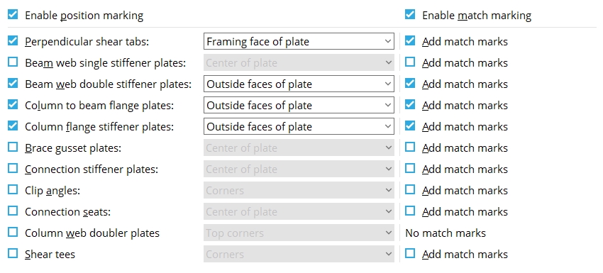
Enable position marking: or . Position marks are placed on the member that the material attaches to in the shop.
If this box is checked ( ), position marking is enabled. The option this selection is made to causes CNC marks to be generated during Create Solids.
If the box is not checked ( ), position marking is disabled.
Enable match marking: or . Match marks come in pairs. One is placed on the material that shop attaches to the member, another is placed at a matching location on the member.
If this box is checked ( ), match marking is enabled, and can be switched on or off for individual cases.
If the box is not checked ( ), match marking is disabled.
Perpendicular shear tabs: Center of plate or Left face or Right face or Framing face of plate. This applies to moment and non-moment single-plate shear connections. It also applies to a shear plate that connects a vertical brace gusset plate to a column. The left face is the surface of the shear plate that faces left on the supporting member's detail. The Framing face of plate is the face of a plate that attaches to the supported beam.
Center
Left face
Right face
Framing face
Add match marks puts a match mark 1/3 the way down the near side of the plate and another mark on the supporting beam or column. The match mark on the member is red in this example. The match mark on the plate is shown here as green. The position marks (Framing face) are black. All marks are shown as black in the model.
Beam web single stiffener plates: Center of plate or Left face or Right face. This applies when an auto base/cap plate or user base/cap plate has been set to Use transverse beam stiffener and the Load on the column is sufficiently low that only a single stiffener is generated. The left face is the surface of the plate that faces left on the member detail.
Center
Left face
Right face
Add match marks puts a match mark 1/3 the way down the near side of the plate and another mark on the beam. The match mark on the beam is red in this example. The match mark on the plate is shown here as green. The position mark (Center) is black and placed at the corner of the clip. You cannot see the upper position mark in this view. All marks are shown as black in the model.
Beam web double stiffener plates: Center of plate or Left face or Right face or Outside faces of plate or Inside faces of plate. This applies when an auto base/cap plate or user base/cap plate has been set to Use transverse beam stiffener and the Load on the column is sufficiently high that two stiffeners are generated. The left face is the surface of the plate that faces left on the member detail. The options Inside/outside faces of plate apply to two plates that are parallel to one another; the surfaces of those plates which face each other are the inside faces; the faces which look away from one another are outside faces.
Center
Left face
Right face
Outside
Inside
Add match marks puts a match mark 1/3 the way down the near side of each plate and another mark on the beam. The match marks on the beam are red in this example. The match mark on each plate is shown here as green. The position mark (Outside) that you can see in this view is black and placed at the corner of the clip. All marks are shown as black in the model.
Column to beam flange connection plates: Center of plate or Top face or Bottom face or Outside faces of plate or Inside faces of plate. This applies to bolted or welded moment flange plates and to stability plates for shear plate connections to a column web. The Top face refers to the top of the plate as it appears on the member detail. The options Inside/outside faces of plate apply to two plates that are parallel to one another; the surfaces of those plates which face each other are the inside faces; the faces which look away from one another are outside faces.
Center
Top face
Bottom face
Outside
Inside
Add match marks puts a match mark on each moment flange plate and other match marks on the column. The match marks on the column are red in this example. Each match mark on a plate is shown here as green. The position marks (Inside faces of plates) are black and placed one inch from the edges of the plate. All marks are shown as black in the model.
Column flange stiffener plates: Center of plate or Top face or Bottom face or Outside faces of plates or Inside faces of plates. This applies when the box for Design for stiffeners is checked for a bolted or welded moment connection to a column flange. The Top face refers to the top of the plate as it appears on the member detail. The options Inside/outside faces of plates apply to two plates that are parallel to one another; the surfaces of those plates which face each other are the inside faces; the faces which look away from one another are outside faces.
Center
Top face
Bottom face
Outside
Inside
Add match marks puts a match mark on each stiffener plate and match marks on the column. The match marks on the column are red in this example. The match marks on the plate are shown here as green. The position marks (Outside faces of plates) are black and placed at the corners of the plate. All marks are black in the model.
Brace gusset plates: Center of plate or Left face or Right face. The left face is the surface of the plate that faces left on the member detail.
Center
Left face
Right face
Add match marks puts a match mark 1/3 of the way down the gusset plate and another mark on the supporting beam or column. The match mark on the member is red in this example. The match mark on the plate is shown here as green. The position marks (Center of plate) are black and placed at the top and bottom edges of the plate. All marks are black in the model.
Connection stiffener plates: Center of plate or Left face or Right face. The example shown below is the vertical stiffener for a plate seat. This also applies to stiffeners for angle seats and end plates. The left face is the surface of the plate that faces left on the detail for the member that the stiffener plate shop welds to.
Center
Left
Right
Add match marks puts a match mark 1/3 of the way down the stiffener and another mark on the member it welds to in the shop. The match mark on the member is red in this example. The match mark on the stiffener is shown here as green. The position marks (Center of plate) are black and placed at the edges of the plate.
Clip angles: Corners. This applies to single and double clip angles. The placement of position marks on clip angles depends on whether the clip angles are set to be Attached to the Supported or Supporting in the shop.
Supported
Supporting
Add match marks puts a match mark 1/3 of the way down (or up) the clip angle and another mark on the supported beam. The match mark on the beam is red in this example. The match mark on the clip angle cannot be seen in this view since it is on the face of the clip angle that frames to the beam. The position marks (Corners) are black and placed at the corners of the clip angle. All marks are black in the model.
Add match marks puts a match mark 1/3 of the way down (or up) the clip angle and another mark on the supporting member. The match marks on the column are red in this example. The match marks on the clip angles are not shown in this view since they are on the framing faces. These two clip angles share the same piecemark, and that is why their match marks do not align.
Connection seats: Center of plate or Top face or Bottom face. This applies to plate seats. The top face is the surface of the plate that faces up on the detail of the column that the seat shop welds to.
Center
Top
Bottom
Add match marks puts a match mark on the seat plate and another mark on the member it welds to. The match mark on the member is red in this example. The match mark on the seat plate is shown here as green. The position marks (Top face) are black and placed one inch in from the edges of the plate.
Column web doubler plates: Top corners or Bottom corners or All corners. This applies when Design for doublers is set for a bolted or welded moment connection to a column flange.
Top
Bottom
All
Note: Column web doublers do not have match marks since they are not needed.
Shear tees: Corners. This applies to shear tees. The placement of position marks on a shear tee depends on whether the shear tee is set to be Attached to the Supported or the Supporting in the shop.
Supported
Supporting
Add match marks puts a match mark 1/3 of the way down (or up) the shear tee and another mark on the supported beam. The match mark on the beam is red in this example. The match mark on the shear tee is shown as green. The position marks (Corners) are black and placed on the beam at the corners of the shear tee. All marks are black in the model.
Add match marks puts a match mark 1/3 of the way down (or up) the shear tee and another mark on the supporting beam or column. The match mark on the member is red in this example. The match mark on the tee cannot be seen in this view since it is on the tee's framing face. The position marks are black in this example. All marks are black in the model.
The position of these form buttons on the screen tells you what settings they apply to. Click here for more information.
You can Copy the settings on this screen, then Paste those settings to a different screen of the same type.
You can Save the settings on this screen to a global folder that is used by your current version of SDS2. Give the file a name that will help other users identify its purpose. You can Load a saved file to replace the settings on this screen with the settings that are stored in the file you select.
When editing multiple screens at the same time, Paste and Load replace mixed entries to a single field with a single entry. Copy and Save ignore fields with mixed entries, treating them as if they have no entry or do not exist.
OK (or the Enter key) closes this screen and applies the settings.
Cancel (or the Esc key) closes this screen without saving any changes.
Reset undoes all changes made to this screen since you first opened it. The screen remains open.
These marks can then be used in the shop to guide the fastening of connection materials to the member. The selections made here also determine the dimension points on member details for system connection shear tabs, stiffeners, gusset plates, etc., even if you do not generate CNC marks on member details.
A CNC mark is shown as an X on members in Modeling that are displayed in a solid form. To get CNC marks on member details, Show marks on details during Detail Members. CNC marks are always shown on the details of submaterials. The location of CNC marks also affects dimensioning on member details.
For CNC with DSTV, a good alternative to position marking is to set Placement lines to All submaterial and Line style to Corners and Scribing block type to BO. This will get you CNC marks at the corners of all submaterial.
When position marks are applied to materials using this window (prior to CNC), they will affect piecemarking. If they are applied when the CNC file is generated (as described in the previous bullet point), piecemarking is not affected.
Settings applied to the Position and Match Marks screen are for your current Fabricator. A different set of settings will apply when you Change Fabricator.
CNC marks (materials are marked with based on this window)
Create Solids (selections on this window are applied during)
Add 3D Hole (alternative to automatic material marking)
), position marking is enabled. The option this selection is made to causes CNC marks to be generated during Create Solids.
), position marking is disabled.